Blog · · Andrii Shylenko
CNC internal corner radius design rules, and how to check them
A CNC-milled pocket can't have sharp vertical inside corners. The end mill is round, so every internal corner gets a radius at least as big as the tool's radius. Make the corner radius a little larger than the tool radius, and at least one third of the pocket depth. Keep pockets no deeper than about four times their width. If a square part has to fit, add dogbone reliefs instead of asking for a sharp corner.
A square corner is a common reason a quote comes back with questions. It means a smaller tool, a slower job or EDM, plus a revision you didn't plan for. This guide gives the rules, their sources, and a way to check a part while you design it.
Contents
- Why internal corners can't be sharp
- Choosing the corner radius
- Deep pockets and tool length
- Floor-to-wall corners
- Mating square parts: dogbone and T-bone reliefs
- Undercuts and setups
- Checking it in kernelCAD
- FAQ
The rules at a glance
| Feature | Rule of thumb | Why |
|---|---|---|
| Vertical inside corner | Radius ≥ ⅓ of cavity depth, and slightly larger than the tool radius | A round cutter can't leave a smaller radius, and a larger one lets it keep moving instead of stopping in the corner |
| Pocket depth | ≤ about 4 × cavity width; 2–3 × tool diameter is comfortable in hard materials | Long tools bend, chatter and clear chips badly |
| Floor-to-wall corner | Sharp, 0.5 mm or 1 mm | These match flat and standard corner-radius end mills |
| Square mating part | Dogbone or T-bone relief, at least the tool radius | The insert seats fully without a sharp corner in the pocket |
| Undercut or side feature | Add a setup, or use a standard T-slot or dovetail cutter | A tool coming from the top can't reach under an overhang |
| Number of setups | 3–4 is usually fine; more gets expensive | Each refixture costs time and adds a small position error |
Sources for each number are linked in the sections below.
1. Why internal corners can't be sharp
An end mill is a spinning cylinder. Where two walls meet, it leaves an arc with the tool's radius. A Ø1 mm cutter still leaves R0.5. As Hubs' design guide puts it, a milled internal corner always has some radius.
A truly sharp corner needs another process, such as EDM. That adds cost and lead time, so it is usually better to change the design.
How kernelCAD helps. The model is a .kcad.ts source file, so the corner radius is a named value with its reason beside it, such as cornerR = 4 // > R3 of a 6 mm end mill. The next person to edit the part sees why, and the fillet survives the cleanup.
2. Choosing the corner radius
Two rules of thumb work together.
Relative to depth. Hubs recommends a vertical corner radius of at least one third of the cavity depth, and suggests going about 1 mm above that so the tool can follow a circular path (Hubs). For a 12 mm deep pocket that means R4 or more.
Relative to the tool. Make the corner a little bigger than the cutter radius. Then the tool sweeps the corner in an arc instead of stopping and changing direction, which marks the wall and loads the tool. Xometry suggests adding 0.02–0.05 in (about 0.5–1.3 mm) to the corner radius, so a 0.25 in tool radius becomes a 0.27–0.30 in corner.
In practice, pick the largest end mill the pocket allows and make the corner 0.5–1 mm larger than its radius. Bigger tools cut faster and bend less, so a generous radius also lowers the price.
How kernelCAD helps. dfm_review checks every vertical inside corner against the end mill you name. It reports both sharp corners and fillets that are too small for the tool, with their positions. That's a check in seconds, not a question from the shop two days later.
3. Deep pockets and tool length
Pocket depth matters as much as the corner. A long, thin cutter bends, chatters and struggles to clear chips. Hubs recommends a cavity depth of up to four times the cavity width. It treats anything deeper than six times the tool diameter as a deep cavity that needs special tooling (Hubs). In hard materials the limit is lower. One titanium guide calls 2–3 × the tool diameter practical with standard tools, and recommends reduced-neck tools and through-spindle coolant from 3 to 5 × (Boze Metal).
Depth and corner radius are linked: a deeper pocket needs a longer tool, which must be thicker to stay stiff, which needs a bigger corner. If a pocket must be deep, step it, so a large tool clears most of it and a small tool finishes only the bottom.
How kernelCAD helps. Because the part is code, the depth can be computed from the tool, for example const pocketDepth = 3 * toolD. The rule then holds when someone changes the tool or the pocket later.
4. Floor-to-wall corners
The edge where the pocket floor meets the wall is a different case. A flat end mill leaves it sharp, and a corner-radius (bull-nose) end mill leaves a small radius. Hubs recommends a floor radius of 0.5 mm, 1 mm or none, because those match standard tools (Hubs).
Don't copy the vertical corner radius onto the floor edge. A large floor fillet needs a ball-nose cutter and many fine passes. Ask for one only when stress or cleaning needs it.
5. Mating square parts: dogbone and T-bone reliefs
Sometimes the pocket has to take a square part, such as a bearing block, a square nut, a sensor or another milled block. A filleted pocket corner stops the part's sharp edge from seating. The fix is a relief cut beyond the corner.
- Dogbone. The cutter goes into the corner along the diagonal until its edge passes through the corner point. Placing the tool centre R/√2 from each wall does exactly that. You get a small round notch that both walls run into (Get It Made).
- T-bone. The relief runs into one wall only. Use it when one wall needs to stay unbroken or a diagonal notch would show. Push it into the part by at least the cutter radius (Get It Made).
If nothing mates with the corner, a plain fillet is simpler.
How kernelCAD helps. A dogbone is four lines of code: one cylinder subtracted at each corner, positioned from the insert size and the tool radius. Change the insert or the tool and every relief moves with it.
6. Undercuts and setups
A 3-axis mill reaches the part only from the direction the tool points. Any face hidden under an overhang is an undercut from that side. That includes a groove in a side wall, a slot under a lip or a cross hole. You have three options:
- Machine it in a second setup, with the part turned so the tool comes from the side.
- Use a standard undercut cutter. Hubs notes that T-slot cutters come in widths from 3 to 40 mm, and that 45° and 60° dovetail cutters are standard (Hubs).
- Redesign so the feature opens upwards.
Three or four setups are usually acceptable; more gets expensive. Features that must line up closely should be cut in the same setup (Hubs).
How kernelCAD helps. dfm_review takes the setups you plan as a list of approach directions. It reports the unreachable area in mm², so you know before quoting whether a part needs one setup or two.
7. Checking it in kernelCAD
The examples below are real runs of the MCP dfm_review tool with processes: ["cnc"]. All four parts are in examples/gallery/cnc-corner-examples.kcad.ts. Change variant to switch between them.
A fillet that suits one tool but not another
A 70 × 50 × 20 mm block with a 40 × 30 × 10 mm pocket and R2.5 corners:
const pocket = box(40, 30, 10)
  .fillet(2.5, { parallel: [0, 0, 1] })
  .translate(15, 10, 10);
return box(70, 50, 20).subtract(pocket);
With the default Ø6 mm end mill (R3) the review fails:
cnc.internal-corner-radius  fail
4 internal fillet(s) as small as R2.5 mm below the R3 mm tool radius
(Ø6 mm end mill); add fillets ≥ R3 mm or use a smaller tool.
The result lists the four tight fillets with radius, axis and location, for example { "location": [52.5, 37.5, 15], "radiusMm": 2.5, "axis": [0, 0, 1] }. Run it again with tool_diameter_mm: 4 and it passes: "All internal corners along the approach axes are ≥ R2 mm." The choice is now clear: a smaller tool and a longer cycle, or R4 corners and a faster job.
A square insert pocket with dogbones
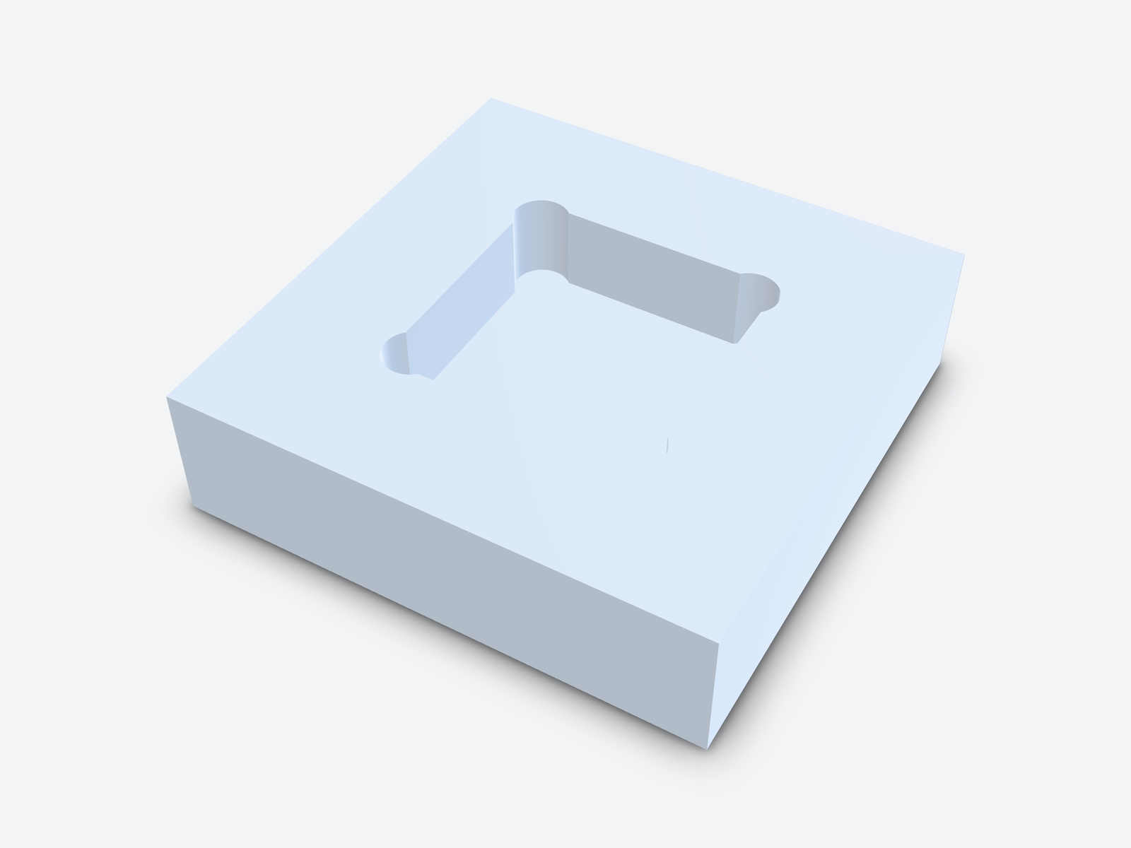
A 30 × 30 × 10 mm pocket for a square insert, with sharp corners, fails the Ø6 check with "4 sharp internal corner(s) (radius 0) below the R3 mm tool radius". It also gives each corner's location, such as [15, 15, 11], and length, 10 mm. Adding an R3.2 dogbone at each corner fixes it:
const d = reliefR / Math.SQRT2; // tool centre on the diagonal
for (const [cx, cy, sx, sy] of corners) {
  part = part.subtract(
    cylinder(depth, reliefR).translate(cx + sx * d, cy + sy * d, plateT - depth),
  );
}
The review passes both checks: "No undercuts: every surface is reachable from the allowed approach axes" and "All internal corners along the approach axes are ≥ R3 mm."
A side groove: one setup or two
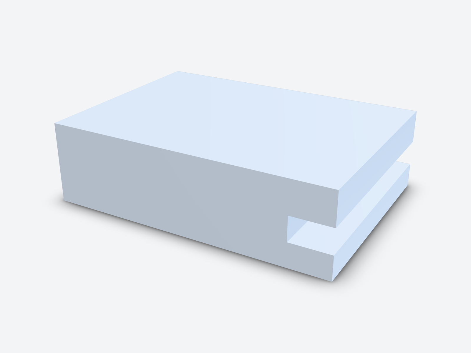
A 10 mm deep, 6 mm tall groove in the side of a 70 × 50 × 20 mm block. From the default approach_axes: ["+z"]:
cnc.undercuts  fail
1300 mm² of surface is unreachable from the allowed tool approach axes;
needs another setup, a 4/5-axis machine or a redesign.
That is the groove floor (500), ceiling (500) and back wall (300). With approach_axes: ["+z", "+x"], a second setup from the side, the verdict is pass.
For the other problems that come up late in a design, see The 10 biggest challenges design engineers face.
Key takeaways
- Every milled inside corner has a radius. Make it at least ⅓ of the cavity depth and 0.5–1 mm larger than the tool radius.
- Keep pockets within about 4 × their width, and lower in hard materials.
- Leave floor corners sharp or use 0.5 mm or 1 mm.
- Use dogbone or T-bone reliefs when a square part has to seat.
- Count setups, and check corners and undercuts against the real tool before you ask for a quote.
8. FAQ
What is the minimum internal corner radius for CNC milling? It equals the radius of the smallest end mill that can reach the corner. For a good price, design for ⅓ of the cavity depth and slightly more than the radius of a common tool size.
Can a CNC mill cut a sharp inside corner? Not in a vertical wall. Use a dogbone or T-bone relief if a square part has to fit, or ask for EDM if the corner really must be sharp.
What is a good pocket depth to tool diameter ratio? 2–3 × the tool diameter is comfortable. About 4 × is a common upper limit for standard tooling, and beyond 6 × counts as a deep cavity that needs special tools.
What is a dogbone fillet? A round relief cut past the corner of a pocket, along the diagonal, so a square part can seat fully. Its radius follows the cutter.
Try kernelCAD free. Connect it to ChatGPT or Claude in a minute: https://app.kernelcad.com/connect